Inertial Measurement Unit and
Compass ...
|
Features:
-
Accelerometers, Three Tri-axial +/- 5 G
-
Rate Gyros, Three Tri-axial +/-
150 degrees/second
-
On chip gyro and accelerometer
temperature sensor outputs.
-
Attitude tracking and gyro righting
software.
Applications
|
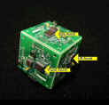
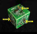
Inertial Solutions linear accelerometers use a
high performance, high accuracy monolithic IC providing a fast
response and low noise. The accelerometer and angular rate gyro
sensors are mounted on the same
small printed circuits panel. Three panels are assembled
orthogonally to form a tri-axial inertial reference.
Modern Attitude Heading Reference Systems use
lightweight, reliable, low power, low cost solid state sensors to
replace spinning mass gyros. Input from three Inertial Solutions
“strap down”
body frame angular rate gyroscopes are rapidly integrated
to track angular position. The position is translated into the local
horizontal frame Pitch, Roll, and Heading (Azimuth) angles.
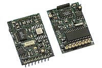
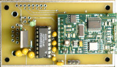
The customer may use the low cost Inertial
Solutions accelerometers and gyroscopes from Analog Devices or may
choose to attach 3rd party gyros or accelerometers to the
connection points at the bottom of the sensor interface card. Power,
ground, and 2.5 V reference are provided to these points. 3rd
party sensors feed into the buffer amplifiers driving the high speed
12 bit analog-to-digital converter on the Processor card.
Normally, the customers navigation computer
receives the 9600 bps serial output
message that reports the Pitch, Roll, and Heading solution 8
times per second. Alternatively, customers may imbed their
application on the Inertial Solution Processor card, thus allowing
processor efficient memory access to inputs and direct control of
motor driven servo output within one system.
Vertical gyro drift is
“righted” by using the difference
between the sum of all accelerations as measured by the
accelerometers (acceleration of gravity plus the acceleration of
motion), and the acceleration of motion as determined by successive
GPS measurements of change in velocity. Hence, corrections to the
vertical are calculated and applied from the running history of the
accelerometer measurements and the GPS sensor input.
Land vehicles "right" the directional gyro using
the GPS horizontal velocity
vector history, when the vehicle is in motion. When
stationary, the directional gyro
is initialized and held by a
Honeywell
HMR3300 three-axis tilt
compensated electronic compass.
The HMR3300 is a three-axis, tilt compensated compass that uses a
two-axis accelerometer for enhanced performance up to a 60° tilt
range. Heading accuracy is 1 degree with 0.1 degree resolution and
0.5 degree repeatability. Tilt range (Pitch and Roll) is +/-60
degrees. Compensation for Hard Iron Distortions, Ferrous Objects,
and Stray Fields.
Compass Users Guide
(244 K)
HMR3300 Spec sheet (227 K)
Magneto Resistive
Sensors (196 K)
Heading, Pitch, Roll
(86 K)
Helicopter (63 K)
Like IMU reports,
Compass data is reported 8 times per second.
Compass - Electronic, 3-Axis
tilt compensated. Origionally $795
|
|
IMU Tri-axial - Three 150 Deg/sec Rate Gyros
and three Accelerometers.
Origionally $695 US customers
only. |
|
10 unsold Units
|